


Op-amp comparators provide a simple way to compare voltages and convert analog signals into clear high or low outputs. They are widely used in threshold-based circuits, but reliable operation depends on understanding their behavior and limits. This article explains how they work, how to configure them, and when they are practical to use.
Comparator Overview
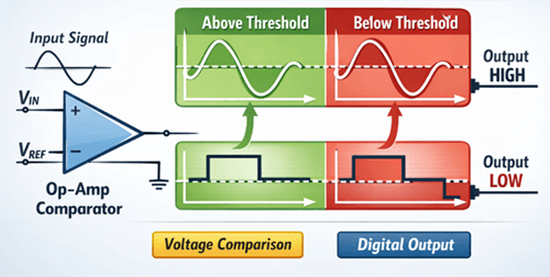
A comparator is a circuit that compares two input voltages and changes its output state based on which one is higher. It turns an analog level into a simple threshold decision by determining whether a signal is above or below a defined reference.
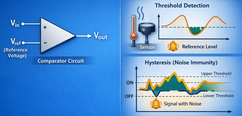
This function is commonly used in threshold detection. For example, a sensor voltage can be compared with a reference level to trigger an action when a condition is reached. In such cases, hysteresis is often added to prevent unstable switching caused by small variations.
How an Op-Amp Works as a Comparator
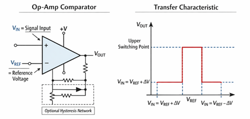
An operational amplifier (op-amp) can function as a comparator when used without feedback. In this mode, it amplifies the voltage difference between its inputs until the output reaches one of its limits.
If the non-inverting input (+) is higher than the inverting input (–), the output goes high. If the opposite occurs, the output goes low. Unlike linear operation, the op-amp is driven into saturation, producing a clear high or low output instead of a proportional signal. The output moves toward the supply rails, though it may not reach them unless the op-amp is rail-to-rail.
To ensure proper operation, input voltages must remain within the op-amp’s common-mode range, even when using a single supply. Once the basic operation is understood, the next step is defining how the comparator is connected and where it switches.
Comparator Configuration and Threshold Design
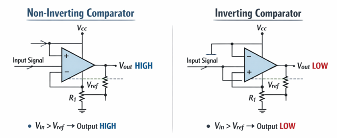
An op-amp comparator can be connected in two common ways: non-inverting or inverting.
Non-inverting Comparator
• Input signal → non-inverting (+) terminal
• Reference → inverting (–) terminal
• Output goes HIGH when input exceeds the reference
Inverting Comparator
• Input signal → inverting (–) terminal
• Reference → non-inverting (+) terminal
• Output goes LOW when input exceeds the reference
The reference voltage sets the switching point. It can be made with a resistor divider in simple circuits, or with a zener or precision reference when better stability is needed. If the reference is not stable, noise or voltage drift near the threshold can cause false switching.
Using Hysteresis for Stable Switching
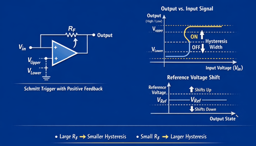
Hysteresis makes a comparator more stable by creating two switching thresholds instead of one through positive feedback. The upper threshold sets the point where the output goes HIGH, and the lower threshold sets the point where the output goes LOW. This Schmitt trigger action helps prevent false switching when the input is noisy or changes slowly.
In a non-inverting comparator, hysteresis can be added by connecting a resistor from the output back to the non-inverting input. This feedback shifts the effective switching threshold depending on the current output state. When the output is HIGH, the threshold moves slightly upward. When the output is LOW, it moves slightly downward. The difference between these two thresholds is called the hysteresis width.
The feedback resistor controls how much hysteresis is added. A larger resistor gives narrower hysteresis, while a smaller resistor gives wider hysteresis. The value should be chosen carefully, because too little hysteresis may not suppress noise, while too much can reduce sensitivity to real signal changes. Hysteresis is especially useful in sensor circuits and other slow-changing input applications that need clean switching.
Op-Amp vs Dedicated Comparator Comparison
| Aspect | Op-Amp Used as Comparator | Dedicated Comparator |
|---|---|---|
| Switching speed | Slower due to limited slew rate and internal compensation | Faster and designed for switching operations |
| Output reaction | Affected by propagation delay | Responds more quickly to input changes |
| Power use | Can be higher when driven into saturation | Usually, better suited for switching efficiency |
| Input range | Limited by common-mode input constraints | Typically designed for a comparator input operation |
| Output level | May not reach ideal rail levels without rail-to-rail capability | Provides cleaner digital-style outputs |
| Signal handling | Can become slow or inaccurate with fast-changing signals | Better for fast and high-frequency signals |
| Output type | Standard op-amp output stage | Often includes open-drain or open-collector outputs |
| Best use case | Simple, low-speed applications | Fast, high-frequency, or timing-critical applications |
Op-Amp Comparator Applications
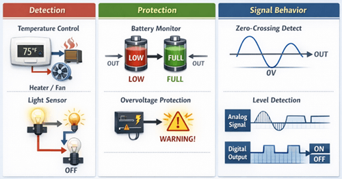
Op-amp comparators are used in circuits that need simple voltage-based decisions, such as:
Detection
• Temperature threshold control — switches a heater, fan, or alarm when a sensor voltage passes a set level
• Light-sensing circuits — detect when ambient light rises above or falls below a chosen threshold
Protection
• Battery voltage monitoring — indicates when battery voltage becomes too low or reaches a required charge level
• Overvoltage or undervoltage protection — triggers shutdown, warning, or isolation when supply voltage moves outside a safe range
Signal Behavior
• Zero-crossing detection — identifies when an AC or changing waveform crosses 0 V for timing or synchronization purposes
• Level detection in analog signals — converts a varying input into a clear ON/OFF output for control logic
In each case, a changing signal is converted into a clear output state that can be used by the rest of the circuit.
Conclusion
An op-amp can function as a comparator for circuits that require simple voltage threshold detection. Reliable operation depends on proper configuration, a stable reference, and the use of hysteresis to prevent unstable switching. However, limitations in speed, input range, and output behavior must be considered. For faster response or more demanding conditions, dedicated comparators provide a more suitable solution.
Frequently Asked Questions [FAQ]
What is the difference between slew rate and propagation delay in a comparator?
Slew rate defines how fast the output voltage changes, while propagation delay is the time between an input change and the start of the output response.
Can an op-amp comparator detect very small voltage differences?
Yes, but accuracy depends on offset voltage and noise. Small differences may require filtering or a precision op-amp.
Why does an op-amp comparator produce a slow or rounded output?
This is caused by limited slew rate and internal compensation, which prevent fast transitions.
When should an op-amp not be used as a comparator?
It should be avoided in high-speed, high-frequency, or timing-critical applications where fast switching is required.
How do you choose hysteresis values?
Set hysteresis wide enough to reject noise but small enough to preserve sensitivity. This is controlled by the feedback resistor ratio and output swing.


