


Power cords may look simple, but the right connector and cable rating directly impact safety, uptime, and compatibility; especially in IT and rack environments. This article explains how IEC 60320 C13 and C14 interfaces work together, and why the C14-to-C13 combination is so common. You’ll also learn how to choose, install, and maintain cables correctly.
Power Cord Overview
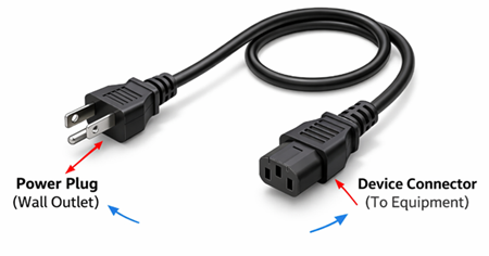
A power cord is an electrical cable used to deliver mains power from a wall outlet or power distribution unit (PDU) to an appliance or piece of equipment. It typically has a plug on one end for the power source and a connector on the other end that mates with the device’s power inlet.
Understanding C13 Power Cord
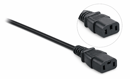
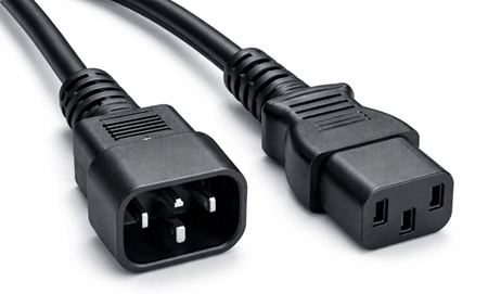
A C13 power cord is a power cable that uses an IEC 60320 C13 female connector, identified by three rectangular slots, designed to mate with a C14 device inlet for supplying AC power to equipment. It is a standardized connector format, which means the same C13 end can fit any device that has a matching C14 inlet. The C13 connector is commonly rated up to 10A at 250V (depending on the cord and regional approvals). Because of this standardization, it is widely used for many everyday electronic and IT devices that require a stable AC power connection.
Exploring C14 Power Connector
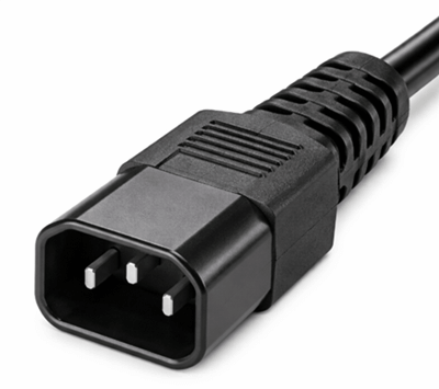
A C14 power connector is an IEC 60320 standardized male connector with three exposed pins, most commonly built into equipment as an AC power inlet. It is designed to mate with a C13 female connector to receive power from a detachable power cord. As a defined connector type, “C14” refers to the inlet/interface shape and pin arrangement rather than a specific cable. In typical use, the C14 is the device-side connection point where mains power enters the equipment.
C13 vs C14 Cord Differences
| Category | C13 | C14 |
|---|---|---|
| Connector Type & Function | Female connector attached to the power cord | Male inlet mounted on equipment |
| Interchangeability | Connects to C14 only | Connects to C13 only |
| Shape & Design | Three rectangular slots | Three prongs (two flat, one grounding pin) |
| Grounding | Accepts grounding pin from C14 | Includes grounding pin for fault protection |
| Typical Electrical Rating (IEC 60320) | Up to 10A, 250V AC | Up to 10A, 250V AC |
| Installation Location | On cable end | Built into device chassis |
| Physical Construction | Cable thickness depends on wire gauge (AWG) and insulation quality | Inlet design fixed; cable thickness determined by current capacity and environment |
| Main Role | Supplies power from outlet to device | Receives power from C13 cable into equipment |
Applications of C13 and C14 Power Connectors
C13 Power Cord
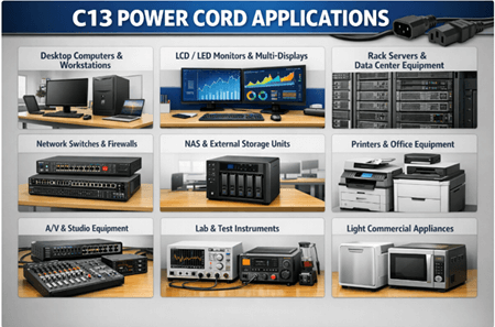
C13 power cords are widely used to supply AC power to equipment that has a C14 inlet. They’re most common in IT, office, and light commercial environments where standardized, removable power leads simplify installation and replacement.
• Desktop computers and workstations for everyday office and commercial use
• LCD/LED monitors and displays, including multi-monitor setups
• Rack-mounted servers (typical standard loads) where 10A-class cords are sufficient
• Network switches, routers, and firewalls in closets, racks, and small data rooms
• NAS and external storage enclosures used for backups and shared storage
• Printers, copiers, and general office equipment that use detachable power cords
• A/V gear such as amplifiers, mixers, broadcast accessories, and studio equipment with IEC inlets
• Lab and test instruments like bench devices, analyzers, and measurement tools that use standardized AC inputs
• Light commercial appliances that rely on removable IEC cords for easy servicing and replacement
C14 Power Connector
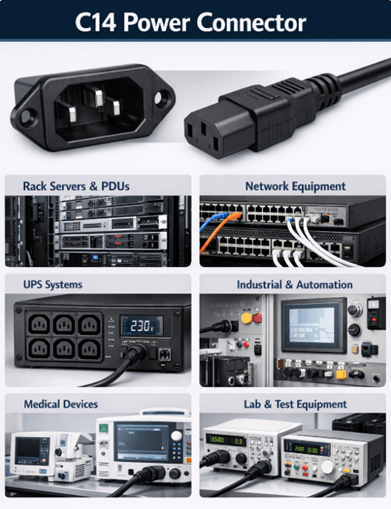
C14 connectors are typically built into the device chassis as the male inlet that receives power from a C13 cord. You’ll commonly see C14 inlets on equipment designed for rack use, standardized cabling, and easy cord replacement.
• Server power supplies and rack servers (commonly 1U–4U equipment) where IEC inlets are the norm
• Enterprise networking hardware including switches, routers, and security appliances in rack deployments
• Power Distribution Units (PDUs) and rack power equipment that distribute power to multiple devices
• UPS systems (many models include C14 inlets/outlets depending on configuration and region)
• Industrial control panels and automation equipment where a standardized chassis inlet improves serviceability
• Medical and laboratory devices that require replaceable, standardized power leads for maintenance and safety checks
• Lab power supplies and instrumentation chassis used in test benches and measurement setups
How to Choose the Right C14 and C13 Power Cable
Verify voltage and current ratings
Start by confirming the cable’s rating meets or exceeds your equipment’s requirements. Many standard IEC C14-to-C13 cables are commonly rated up to 10A at 250V, and pushing beyond the cable’s limits can cause overheating, insulation damage, or premature failure. A correctly rated cable keeps power delivery stable and protects both the cord and the device over long-term use.
Check the wire gauge (AWG)
Wire gauge determines how much current the cable can carry safely. A lower AWG number means thicker wire, which reduces resistance, runs cooler under load, and minimizes voltage drop. This matters most for equipment that operates continuously—such as servers, switches, and rack gear—where undersized conductors can lead to excess heat and unreliable performance.
Choose the right cable jacket type for the environment (SJT vs. SOOW)
Match the cable type to where it will be used. SJT is typically suitable for offices and light commercial areas with controlled conditions and minimal mechanical stress. SOOW is built for tougher environments, with a more rugged jacket designed to handle oil exposure, moisture, abrasion, and temperature changes. Choosing the correct jacket improves durability and reduces safety risks in demanding installations.
Benefits of Using C14 and C13
• Simplified cable management: Because C14 and C13 are standardized, they help reduce cable clutter and keep racks and work areas clean and organized.
• Reliable power delivery: A secure C14-to-C13 fit supports steady, consistent power transfer for compatible equipment.
• Lower downtime risk: Standard compatibility makes it faster to swap cables, restore power, and troubleshoot issues during maintenance.
• Easy scalability: You can add, move, or reconfigure devices in racks more quickly without changing the overall power setup.
• International compatibility: The IEC standard design and common 10A, 250V rating make these connectors widely usable across many regions and environments.
• Better airflow in dense setups: Cleaner cable routing reduces blockage, helping cooling systems move air more efficiently.
• Simplified maintenance: A structured power layout makes inspections, upgrades, and expansions quicker, safer, and easier to manage.
Maintenance Tips for C13 and C14 Power Cables
To extend service life and keep operation safe:
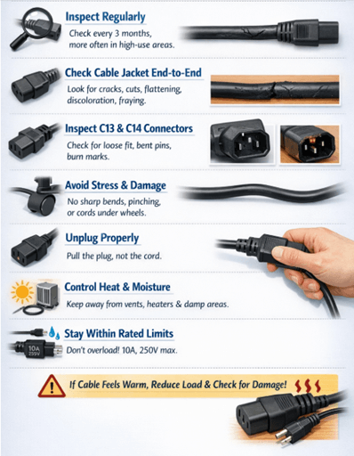
• Inspect regularly: Check cables at least every 3 months, and more often in high-use areas like server rooms, workshops, or shared office setups.
• Check the cable jacket end-to-end: Look for cracks, cuts, flattening, discoloration, or fraying—especially near the strain-relief points close to each connector.
• Inspect both ends (C13 and C14): Watch for looseness, bent pins, melted plastic, burn marks, or a wobbly fit when plugged into the inlet/outlet.
• Prevent stress and damage: Avoid sharp bends, pinching, and constant tension. Don’t run cords under chair wheels, through door gaps, or beneath heavy equipment. When unplugging, pull the connector body, not the cable.
• Control heat and moisture exposure: Keep cords away from hot exhaust vents, heaters, direct sunlight, and damp floors or wet areas.
• Stay within rated limits: Do not exceed the cable’s rating (commonly 10A, 250V for standard C13/C14). If the cord or connector feels warm during use, reduce the load and check for poor contact, damaged connectors, or undersized wire gauge.
Step-by-Step Installation Tips for C13 and C14 Power Cables
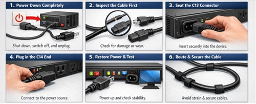
• Power down completely: Shut down the equipment properly, switch off the PDU/UPS (if available), and unplug from the outlet to avoid handling a live connection.
• Inspect the cable first: Check the entire cord for cuts, cracks, or fraying. Inspect both connectors for loose housings, bent contacts, or heat discoloration. If anything looks damaged, replace the cable.
• Seat the C13 connector securely: Align the C13 correctly with the device’s C14 inlet and push it in firmly until fully seated. A tight fit helps prevent intermittent power, arcing, and heat buildup.
• Plug the C14 end into the power source: Insert the C14 into a compatible IEC outlet on a PDU, UPS, or other approved power interface. Ensure it sits flush and does not wobble.
• Restore power and confirm stability: Reconnect the main power, switch on the power source, and power up the device. Verify normal startup and ensure the connection remains steady during operation.
• Route and secure the cable properly: Avoid sharp bends, pinch points, and hot surfaces. Leave slight slack for strain relief and secure the cable with Velcro straps or ties to reduce pull-out and tripping risks.
Never force connectors into the wrong port. Use a cable with the correct rating for the load, and avoid overloading circuits—especially when multiple devices share the same PDU or outlet.
C13/C14 vs Other IEC Connector Types
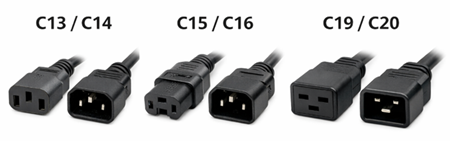
| Aspect | C13 / C14 | C15 / C16 | C19 / C20 |
|---|---|---|---|
| Connector Gender (Cord / Device) | C13 = Female (cord) / C14 = Male inlet (device) | C15 = Female (cord) / C16 = Male inlet (device) | C19 = Female (cord) / C20 = Male inlet (device) |
| Typical Current / Voltage Rating* | Typically,10A @ 250V (varies by region/spec) | Commonly10A @ 250V (often rated forhigher temperature environments) | Commonly16A @ 250V |
| Key Physical Feature | Standard “computer power” shape; general-purpose | Notched/“keyed” design vs C13/C14 to support higher-heat use | |
| Larger, heavier connector body than C13/C14 | |||
| Common Use Cases | Desktop PCs, monitors, printers, small servers, network switches, many office/IT devices | Electric kettles, some hot-running kitchen appliances, certain heated equipment | High-power servers, blade server chassis, enterprise networking, PDUs, UPS systems |
| Why You’d Choose It | Best all-around option for everyday equipment wherestandard temp + moderate power is enough | Choose when the device inlet is designed forhigher operating temperatures, reducing heat-related risk | Choose forhigher current draw equipment where C13/C14 may be undersized |
Common Mistakes When Choosing C13 and C14 Power Cables
| Common Mistake | Why It’s a Problem | Best Practice / How to Avoid It |
|---|---|---|
| Ignoring current rating limits | Most standard C13/C14 cables are typically rated10A, 250V. Overloading can cause overheating, insulation breakdown, and fire risk. | Check the device’s actual current draw and keep the cable/load within its rated limits. |
| Choosing the wrong wire gauge (AWG) | Thinner wire increases resistance, leading to voltage drop and heat buildup—especially with continuous operation. | Match AWG to load and duty cycle:18 AWG (lighter loads),16 AWG (continuous/moderate loads),14 AWG (heavier-duty). |
| Overlooking environmental conditions | Indoor-rated jackets can crack or fail in heat, moisture, oil, or mechanical stress, reducing safety and lifespan. | Choose insulation for the environment:SJT for office/light use;SOOW for oil/moisture and tougher industrial conditions. |
| Selecting the wrong regional plug type | C13/C14 only defines the equipment-side connector; a mismatched wall plug can force unsafe adapter use or prevent connection. | Confirm both ends: C13/C14 sideand the correct regional plug (e.g.,NEMA, Schuko, UK). |
| Using excessively long cables | Longer runs increase resistance and voltage drop; extra slack in racks can block airflow and worsen cable management. | Use theshortest practical length for cleaner routing, better airflow, and reduced heat/voltage drop. |
| Ignoring certification and compliance | Uncertified cables may fail insulation, grounding, or fire-resistance requirements and can create liability/warranty issues. | Buy from reputable suppliers and look for marks likeUL,RoHS, and relevant local approvals. |
| Forcing incompatible connectors | Similar-looking IEC types (e.g., C15, C19) are not interchangeable; forcing can damage inlets/connectors and create hazards. | Verify the connector type before installation; never force a connector that doesn’t seat smoothly. |
| Failing to inspect cables regularly | Wear can be hidden: frayed insulation, loose connectors, or bent ground pins can cause intermittent power or safety risks. | Do periodic checks (especially in high-load areas): look for damage, looseness, heat discoloration, and bent pins; replace when needed. |
Conclusion
Choosing a C14 and C13 power cord is more than matching shapes; it’s about selecting the correct rating, wire gauge, jacket type, and certified build quality for the environment. When properly specified and installed, these standardized IEC connectors simplify rack power distribution, improve cable management, and reduce downtime risk. Follow the safety, compliance, and maintenance steps to keep equipment powered reliably and securely.
Frequently Asked Questions [FAQ]
Q1. Can I use a C13 power cord for high-power servers or blade systems?
Not always. Standard C13/C14 cables are typically rated for 10A at 250V, which is suitable for most desktops, monitors, and small servers. However, high-power servers, blade chassis, or enterprise equipment may require C19/C20 connectors rated for 16A or higher. Always verify the device’s input current rating before selecting a cord.
Q2. What happens if I use an underrated C13/C14 power cable?
Using a cable with insufficient current capacity can cause overheating, insulation breakdown, connector melting, and potential fire hazards. It may also lead to intermittent power loss or equipment shutdown. To prevent damage, match the cable’s amp rating and wire gauge (AWG) to the device’s continuous load requirements.
Q3. Are all C13 to C14 power cords the same quality?
No. While the connector shape is standardized under IEC 60320, build quality varies by manufacturer. Differences include copper purity, wire gauge accuracy, insulation thickness, molding quality, and certification compliance. Choosing UL-listed and properly rated cables from reputable suppliers ensures safer, longer-lasting performance.
Q4. How long can a C14 to C13 power cable be without causing voltage drop?
Cable length affects resistance and voltage stability. For typical 10A loads, shorter lengths (1–3 meters) are ideal in rack environments. Excessively long cables increase resistance, heat buildup, and clutter. In high-density data centers, selecting the shortest practical length improves airflow, efficiency, and reliability.
Q5. Can I plug a C13 connector into a C15 or C19 inlet?
No. Although some connectors may look similar, they are not interchangeable. A C13 fits only a C14 inlet. C15 connectors are keyed for higher-temperature applications, and C19/C20 connectors are larger and designed for higher current loads. Forcing mismatched connectors can damage equipment and create safety risks.


